I’ve accidentally left our garage door open a few times. To combat this I built a monitor that sends an alert via Mattermost when the door has been left open for more than 5 minutes. This turned out to be a super fun project. I used parts on hand as much as possible, implemented the monitoring application in Rust, and then built a stripped down Linux image to run it.
Overview & Goals
The garage door state is monitored via a reed switch. If the door is left open for more than 5 minutes a message is posted to a Mattermost channel. The monitor has a web server that allows the current state to be viewed (on the local network only). There’s also a JSON endpoint that I use to put the door state in the status bar of my Awesome desktop. An LED on the device flashes to indicate status around once every second. All code and designs are published in a git repo.

When I embarked on this project I researched the garage door opener that opens and closes the door. The installation document mentions an “E-Serial port” but it’s listed as an input. I concluded that the opener doesn’t readily expose the door state and proceeded with tracking this myself.
I had a few goals in mind, which shaped the approach:
- Notify both my partner and I when the door is left open.
- Use parts I had on hand as much as possible.
- Minimise upkeep/maintenance of the final result.
For notifications I made use of the Mattermost instance I host. I created a channel called House and then created an incoming webhook locked to that channel. The garage door monitor uses this web hook to post messages.
It was important that the monitor be able to send notifications so that we would be alerted even if we were away from home. For example, if we left in the car but forgot to close the door. Without this requirement it would have been enough to wire an LED directly to the reed switch that could be observed from inside the house.
Making https requests means the monitor needs to be able to access the internet. With the parts I had on hand this meant an Espressif ESP32 or Raspberry Pi Zero W. The ESP32 would be perfect except I prefer to write software in Rust and after some investigation I concluded Rust on ESP32 is still immature, although improving every month.
So Pi Zero it was. The Pi Zero in question is actually the one I used for my e-Paper conference badge in 2019.
Software
The software came together quickly. I used a thread per task approach where there is a dedicated thread for each of:
- General-purpose input/output (GPIO)
- Monitors the door state and controls the status LED.
- State management
- Receives updates from the GPIO thread via a channel and detects door state transitions.
- Updates the global state when a change is detected and notes the time the door was opened if the state transitions to open.
- Notification thread
- Checks the global state every 5 seconds and sends a notification if the door has been open for more than 5 minutes.
- Notes the notification time to prevent repeatedly sending the notification.
- HTTP server
- Serves the web page and JSON endpoint.
- Main thread
- Polls a flag every 5 seconds in order to detect signals and shutdown cleanly (mainly useful during development).
Acquiring access to the GPIO pins requires elevated privileges, so after that’s done the application drops privileges to a regular user.
All logging is done via syslog to avoid the need to manage an application specific log file. The logging was mainly used during development. The only way to see it is via the serial console.
Web Server
A failure mode of this whole arrangement is that if it stops working for some reason I won’t know unless I observe the status LED. To remedy this I included a web server that allows the status of the device to be checked remotely (on the local network) via a web page.
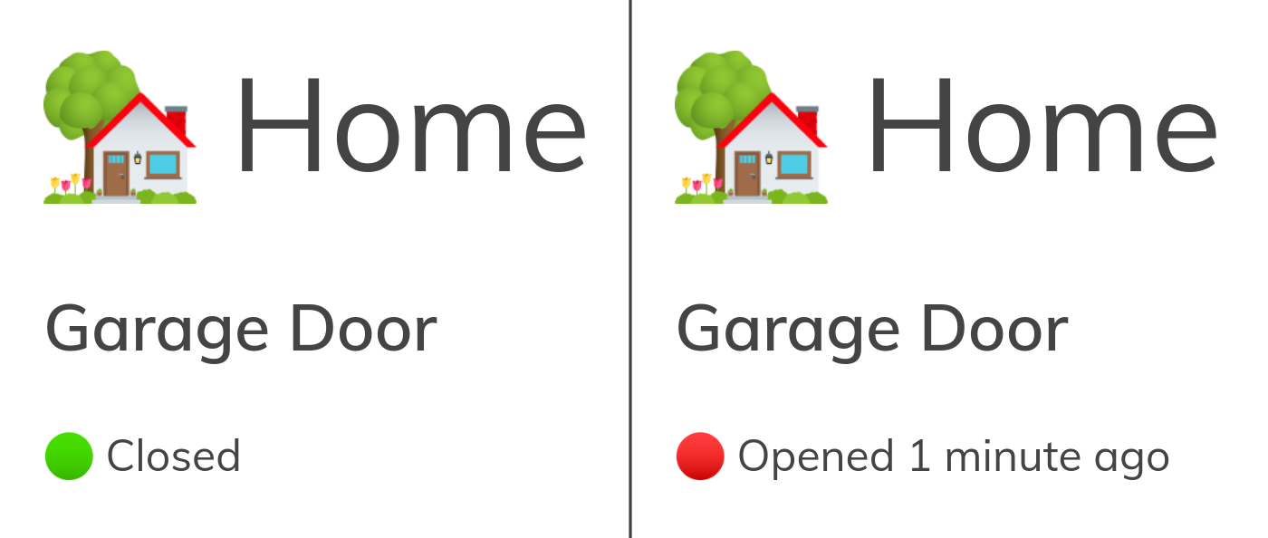
I then extended this with a JSON endpoint /door.json:
{
  "state": "Open",
  "secs_since_notified": null,
  "open_for": 9
}
I use the JSON endpoint in my status bar to show the door status:

- 🚪: Closed
- 🪟: Open
- 🚪❓: State unknown
- 🚪⁉️: Error fetching status
Shrinking/Hardening/Buildroot
The trouble with using a Raspberry Pi is now I have another computer I have to maintain: apply package updates, upgrade the OS, worry about wearing out the SD card, etc. Raspberry Pi OS was great for getting the project off the ground but I wanted to slim it down so it was running the bare minimum amount of software. I also wanted it to run from RAM so that I didn’t have to worry about the SD card wearing out or file-system corruption from unclean shutdowns.
The aim was to turn the Pi into a glorified microcontroller that I could feel comfortable running for years without needing to worry about applying updates etc. Yes it’s still possible that there is a vulnerability in the limited amount of software it runs but I feel like I’ve reduced the attack surface enough that I can happily let this thing run and it’ll be fine.
I used Buildroot to build a custom Linux file system image. I started with the base Buildroot Raspberry Pi Zero configuration and then trial-and-error disabled kernel features and tested that it still worked. The image started off at about 30Mb and ended up at 13Mb. The smallest microSD card I could get my hands on was 256Mb (thanks Kim), so the aim wasn’t really the smallest image possible, more the most basic kernel configuration that would still run the application.
In the end I disabled a lot of kernel features, including:
- Ethernet devices, IPv6, Bluetooth, BPF, netfilter, cifs, nfs, PPP and other network protocols and devices
- Most file systems, SCSI
- I2C, 1-wire, sensors devices
- Display support
- Quotas, accounting
- USB, virtio, sdio, IR, PPS, HID
- MD (LVM/RAID) and MMC block devices
- Sound and multimedia devices, game controllers, etc.
The resulting image boots and is interactive in under 5 seconds. The monitoring application itself starts running about 13 seconds after power is applied, as shown in the video below. The time between boot and the application running is taken by bringing up the Wi-Fi connection and syncing the clock.
The image runs entirely from the initial RAM disk embedded in the kernel image. The SD card is not even mounted, nor can it be mounted as the kernel lacks the necessary file-system support. The Raspberry Pi bootloader loads the kernel and initial RAM disk into memory from the SD card, then hands over to the kernel.
The final image includes the following:
- Linux kernel
- musl libc
- Busybox
- Raspberry Pi Firmware
- OpenNTPD — for syncing the clock
- wpa_supplicant — for Wi-Fi
- daemon — process supervisor to restart
the
garage-door-monitorbinary if it exits for some reason. - garage-door-monitor — the application itself
- rsdate — for setting the clock at boot
Since the image lacks ssh, debugging was done over a serial console (which
is protected by a password) while I iterated on the Buildroot image.
OpenNTPD and rsdate are used for time keeping. Semi-accurate time is
required to make https connections to Mattermost.
OpenNTPD removed its functionality for syncing the time at startup
and since the Pi Zero lacks a real-time clock it boots up with the time set to
the distant past. The delta is greater that OpenNTPD is willing to adjust for
so the time remains in the past. To address this I built rsdate, a small Rust
tool that sets the system clock to the time retrieved from an ntp server. This
is run at boot and afterward OpenNTPD takes care of keeping it in sync.
Buildroot has built-in support for Rust so as part of the building the image it
also cross-compiles the monitoring application and rsdate and bakes them into
the image.
I ran the image in my study for a couple of weeks occasionally flipping the door state by adding or removing a resistor on a breadboard to help ensure it was working properly.
Hardware
Wiring
The diagram below shows the limited wiring required:

- The Pi is powered through header pins 4 (5V) and 6 (GND).
- A reed switch is connected between pin 1 (3.3V) and pin 38 via a 10kΩ resistor. Internal pull-downs are enabled on this pin.
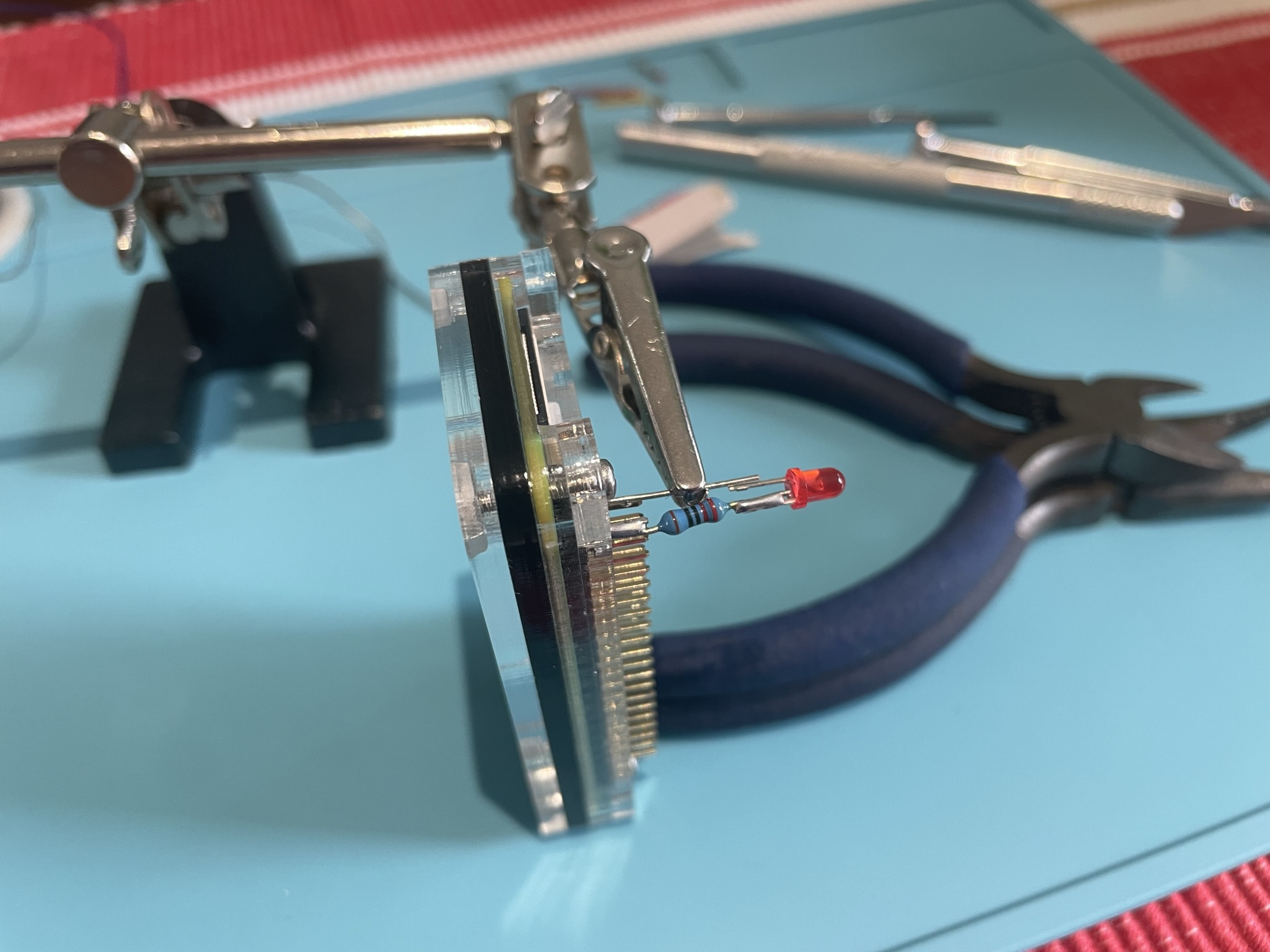
- The anode of a 3mm LED is connected to header pin 40 via a 220Ω current limiting resistor. The cathode is connected to pin 39 (GND)
The pin for reading the reed switch is configured so that if the reed switch is missing or broken then it will be detected as the door being open and an alert eventually sent.
Status LED
The LED periodically blinks to show the state of the device. This allows correct operation to easily be observed in person.
- No blinking: something is wrong
- Perhaps the application is not running or there was a permission issue accessing GPIO. In the latter case other components of the application like the web-server continue running so there are other ways to check what is happening.
- One blink: Door closed
- Two blinks: Door open
- Three blinks: Door state unknown
Installation
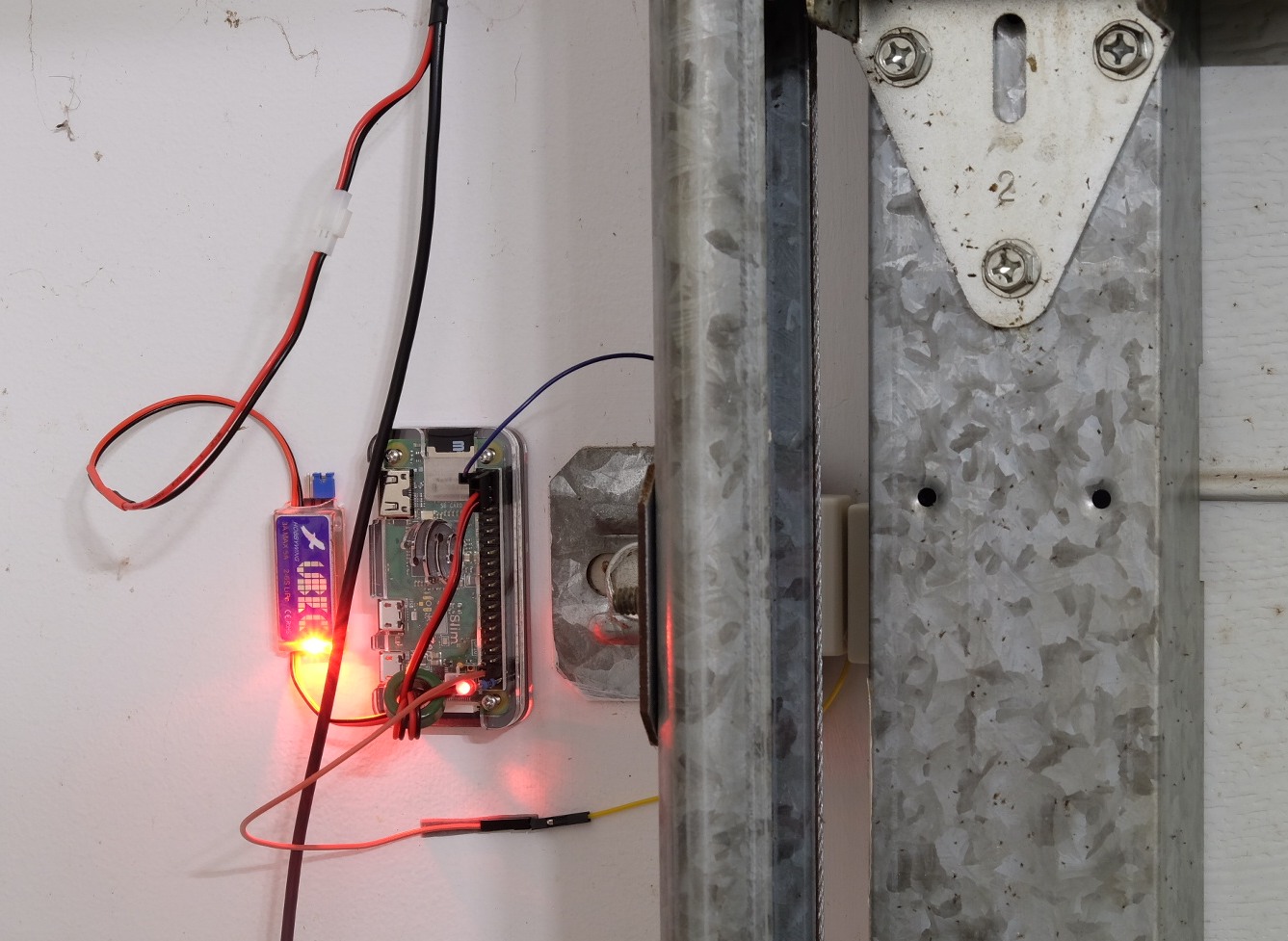
Our house came with a security system and there is a camera mounted on the front of the garage. The cable that runs to the camera goes right past where I wanted to put the garage door monitor and it carries 12V DC. To power the Pi from that I bought a UBEC on AliExpress for US$1.94.
The UBEC is a tiny switch-mode power supply intended for powering the receiver and servos in remote control planes, etc. It’s perfect for the Pi too: It’s rated at 3 amps, outputs 5V and can take a broad range of input voltages.
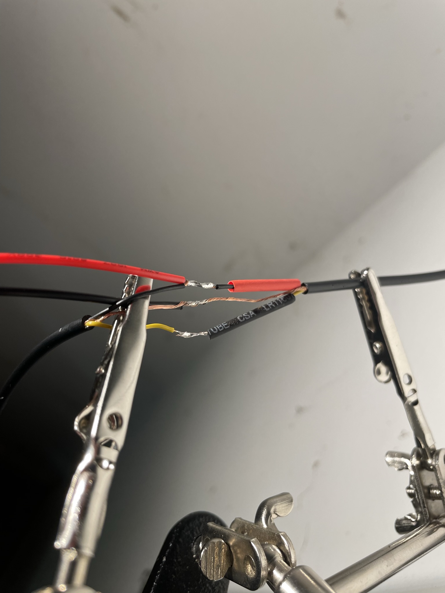
I cut the camera cable and spliced a little connector into it for the BEC to connect to. This turned out to be extremely fiddly and time consuming, requiring three attempts before I got a result I was happy with.
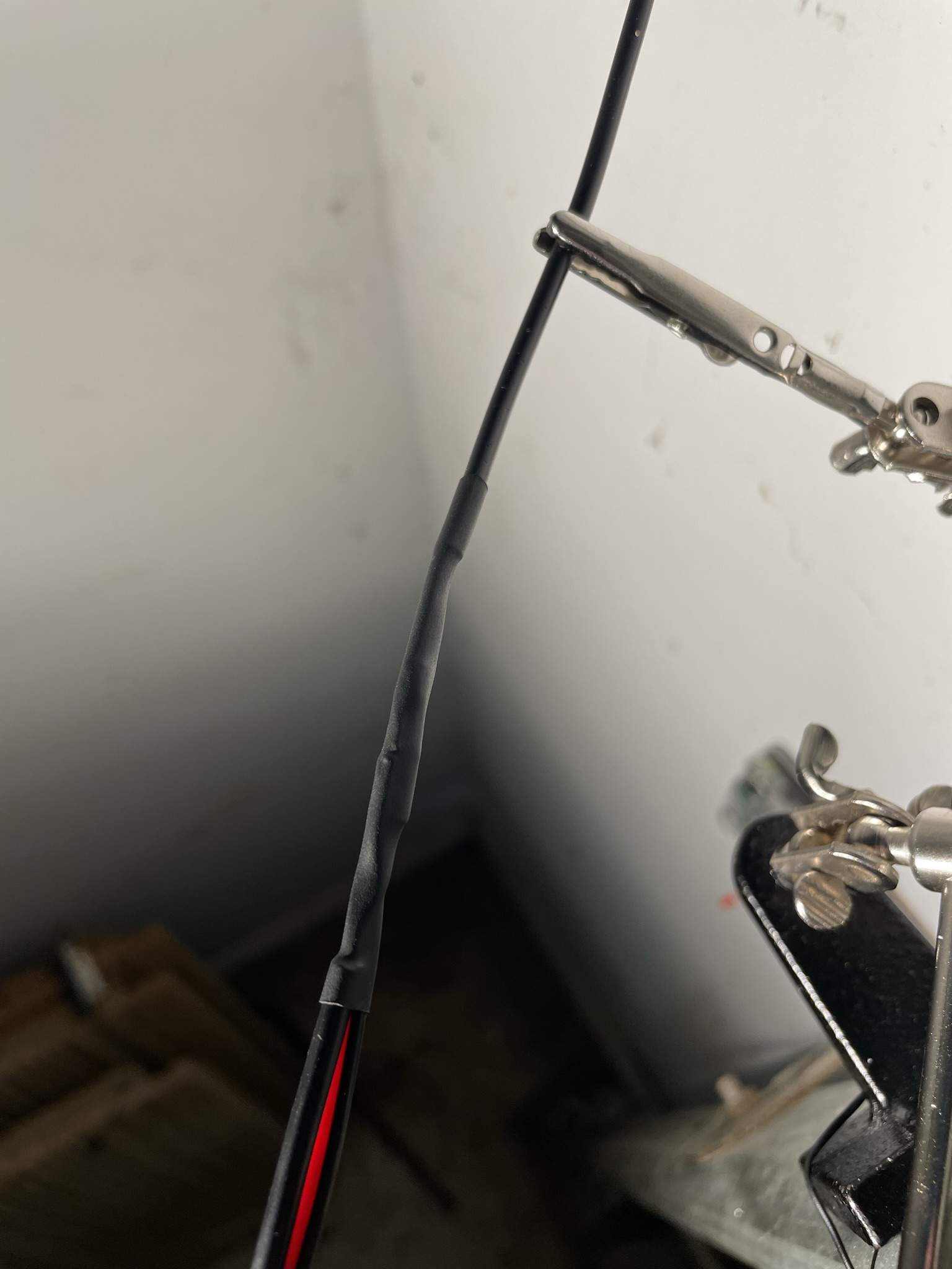
The only other part I had to buy for this project was the reed switch. I picked this up from the local Jaycar for about AU$5. I mounted it between a bracket that holds the runner for the garage door and the door itself. The gap was too wide for the reed switch to operate so I designed a spacer in FreeCAD and 3D printed it. It’s a block with 3mm holes and slots in the sides for nuts to slide into. You can view the rendered model on GitHub.
The first revision of the spacer was too tall and the slots for the nuts weren’t quite big enough—I’m still new to 3D modeling and 3D printing. I tweaked the design (yay for parametric modeling) and printed a second version, which worked well.
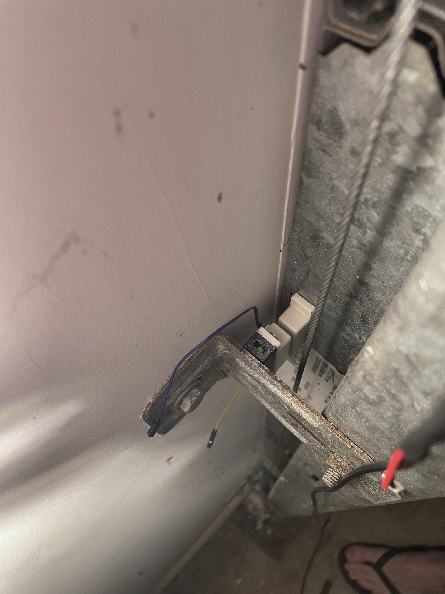
I used super sticky double sided tape to attach everything to the wall and bracket.

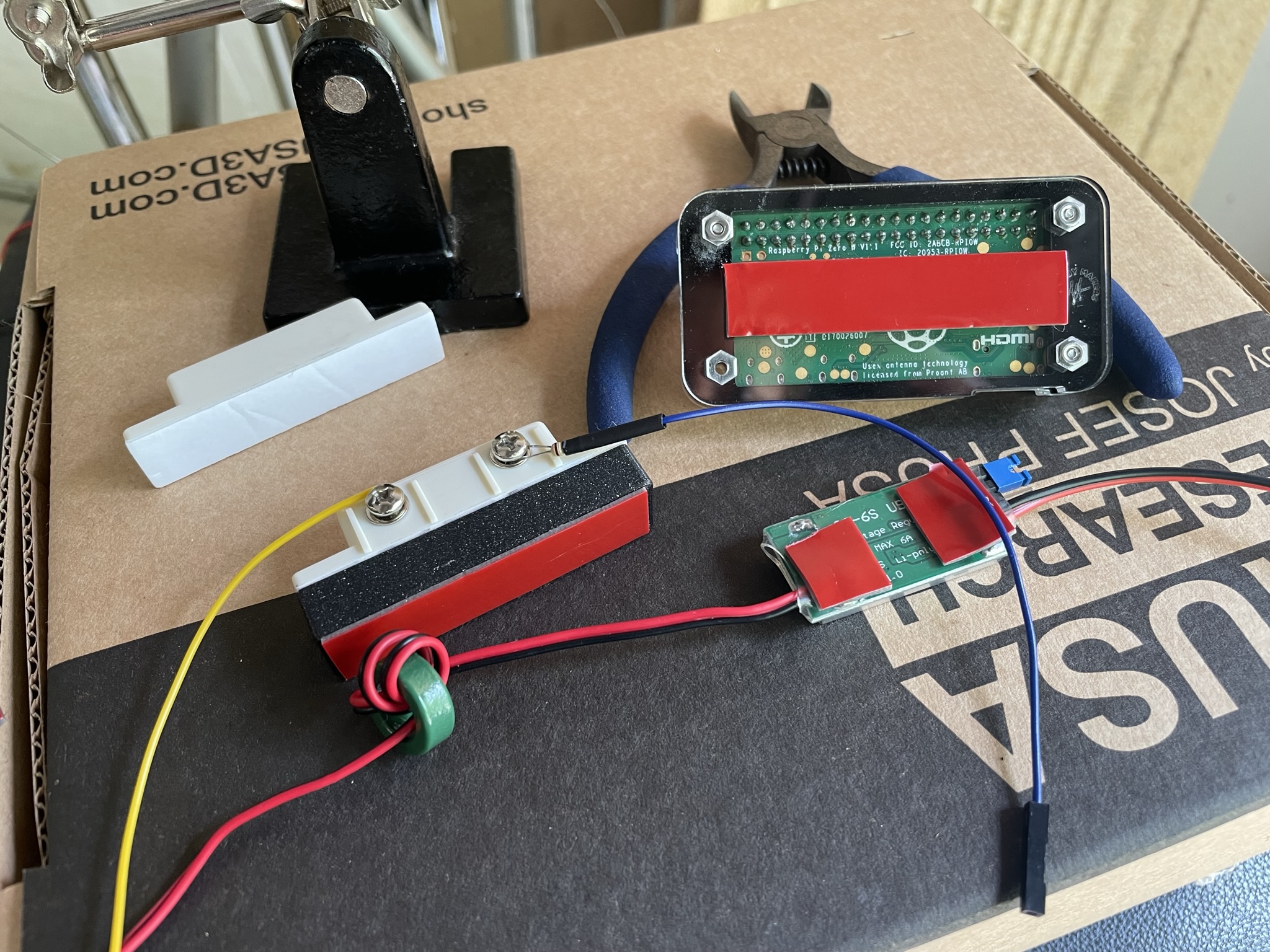
Before connecting the Pi to power I tested the BEC output and reed switch behaviour with a multimeter. I used washers under the reed switch to fine tune the gap between it and the magnet attached to the garage door to ensure it switched properly. Once all seemed well I connected the Pi and tested that the monitoring, web server, and notifications were working as expected—they were!
Conclusion
This was a fun project as it combined several of my interests: hardware and electronics, software, web dev, and operating systems. I’m pleased with the end result. It’s certainly not the smallest Linux system in the world but definitely a lot smaller than Raspberry Pi OS Lite.
The true test will come if/when I leave the door open and receive a notification, making all this worth it. I’ll post an update if that happens.
All the code, hardware designs, and Buildroot configuration/overlay is available in the git repository if you’re interested.
See part two for a couple of new features I added a few months later.